D-Robotics D-Robotics · Computing and Control
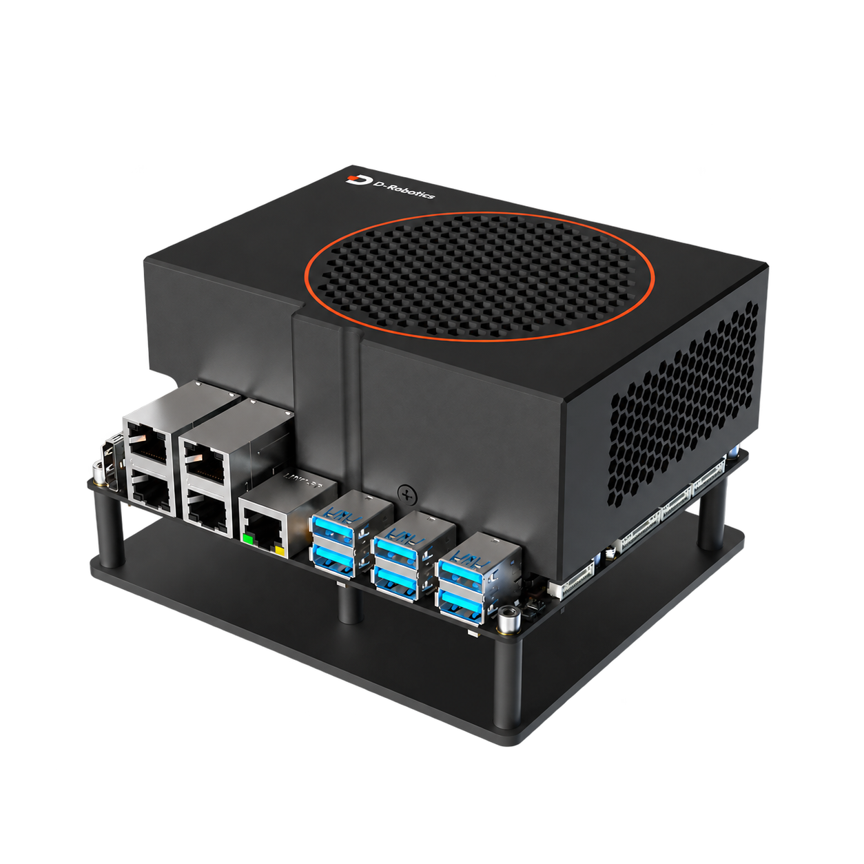
D-Robotics RDK S100P
Configurations in the S100 series for higher computing and memory requirements are suitable for reserving more resources for vision, positioning and robotics applications.
Development platforms and accessories
Overview
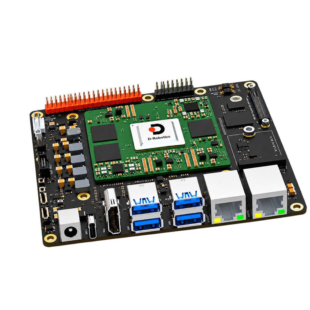
- 128 TOPS BPU (equivalent to INT8) and 24 GB LPDDR5
- 6 × Cortex-A78AE @ 2.0 GHz;4 × Cortex-R52+ MCU
- Dual Gigabit Ethernet, camera extension and MCU extension
- 64 GB eMMC and M.2 NVMe expansion, four-way USB 3.0
Typical tasks
- multi-camera vision algorithm
- Roboticsperception and positioning calculation
- complex model and multi-task development
What to consider
- Compare memory capacity, compute resources and target workloads with S100.
- Multi-camera designs must consider connectivity expansion, bandwidth, synchronization and cooling together.
- chassis communication and perception data are recommended to separate interface responsibilities.
RDK official accessories for this console
First determine the accessory model, and then check the interface, installation, power supply and software version. The following is the scope of application specified by the manufacturer. Continue to check the complete connection combination during configuration.
Specifications & Interfaces
| Compute platforms | D-Robotics RDK S100P (6 × Cortex-A78AE @ 2.0 GHz) |
|---|---|
| Compute performance | BPU:128 TOPS
GPU:100 GFLOPS Conditions
|
| Memory | 24 GB LPDDR5 |
| Storage & Expansion | Storage and expansion: 64 GB eMMC
Storage expansion interface: M.2 Key M, PCIe 3.0 × 1 |
| Camera connectivity | Camera expansion interface: Camera Expansion Header
Mainboard camera expansion link: 1×Camera Expansion interface, providing 3 × 4-lane MIPI CSI-2 signals Conditions
|
| Wired network | 2 × Gigabit RJ45 |
| CAN interface | MCU 100-pin connector leads to CAN5 / CAN6 / CAN7 / CAN8 / CAN9 Conditions
|
| Power supply | 12–20 V DC |
| Dimensions & Weight | 120 × 121 × 51 mm |
| Operating environment | 0–45 °C |
Additional memory & Storage
| Other memory parameters | 96-bit |
|---|
Other power & installation specifications
| Other power supply parameters | Motherboard power connector: inner diameter 2.5 / outer diameter 6 mm
Peak and minimum power capabilities: upper limit of board input 150 W; extreme scenarios recommended 150 W (20 V / 7.5 A)
Current and conditions: typical scenarios 5.5 A @ 12 V; extreme scenarios 7.5 A @ 20 V Conditions
|
|---|---|
| Heat dissipation form | Support fan speed control; 12 V fan interface maximum 200 mA Conditions
|
Additional compute specifications
| GPU model | Mali-G78AE |
|---|---|
| Real time MCU | 4 × Cortex-R52+ @ 1.2 GHz |
Other interfaces & features
| Wireless and Expansion | M.2 Key E:PCIe 3.0 × 1 + UART |
|---|---|
| USB and flash interface | USB Host: 4 × USB 3.0
Flashing and debugging: 1 × USB 2.0 Type-C |
| Display and audio and video | HDMI 1.4, up to 2K @ 60 Hz |
| Control and expansion interface | Main domain extension: 40-pin GPIO, Camera Expansion Header, Auto Header
MCU extension: 16-pin MCU GPIO, MCU Port Expansion Header
Debugging: JTAG |
Components & Accessories
Product & configuration scope
- RDK S100P Compute platform
- Select expansion and storage configurations for the perception task
Accessory selection
- model matching power supply and heat dissipation structure
- Camera Expansion Board, Cable Harness and Fixtures
- Network and control interfaces for positioning or chassis connections
Included items, options, wiring harnesses and mounting hardware are confirmed according to the selected model and system configuration.
Software and usage support
- Use the official system and toolchain for S100P.
- camera driver and inference model maintain version correspondence with the ROS component.
- Record the actual operating configuration for future expansion and maintenance.
Operating conditions
- The input power range is 12–20 V DC; expansion cameras, wireless modules and MCU peripherals should check the supporting board and pin definitions.
Technical resources
When using these documents, please check the product model, hardware configuration and document version.
Learn about related components
Explore the compute, perception and mobile platforms used in related solutions; see each solution for compatibility conditions and options.