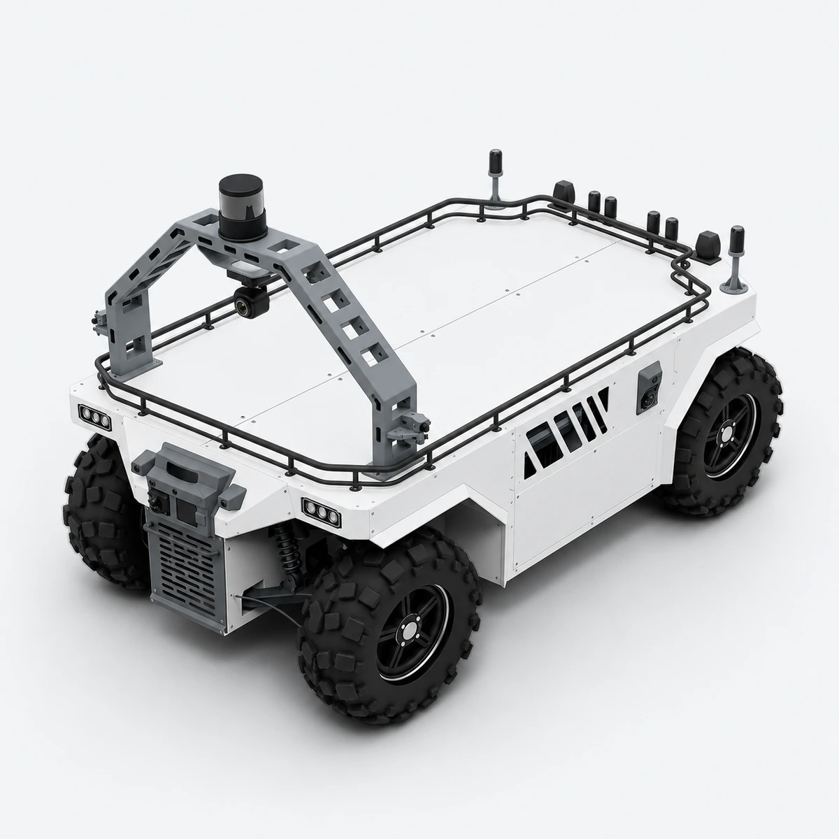
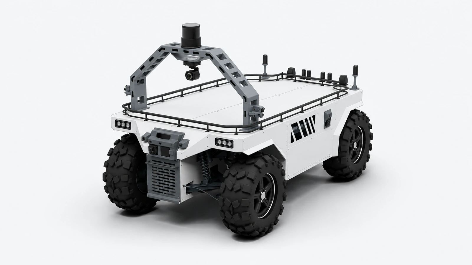
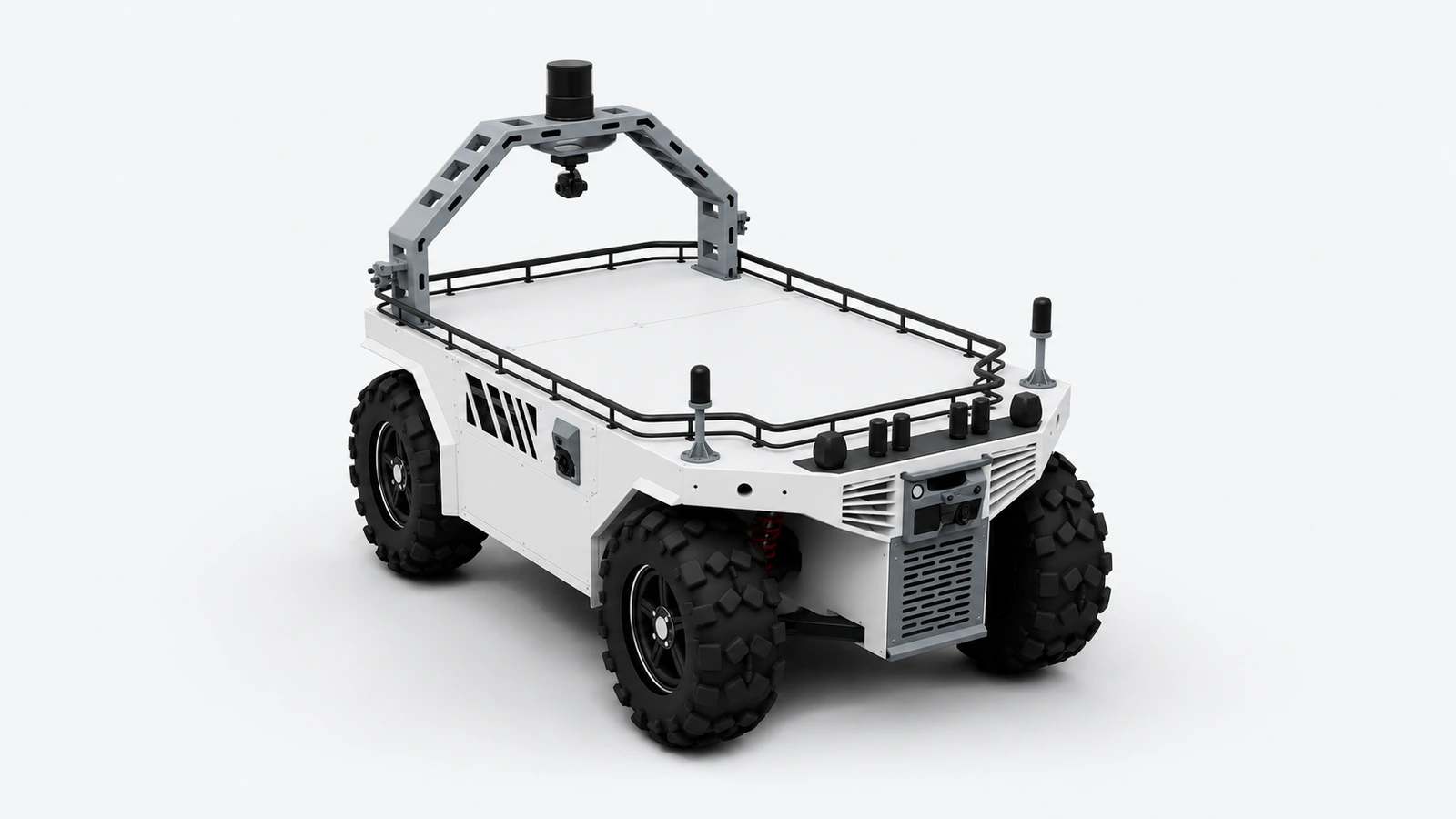
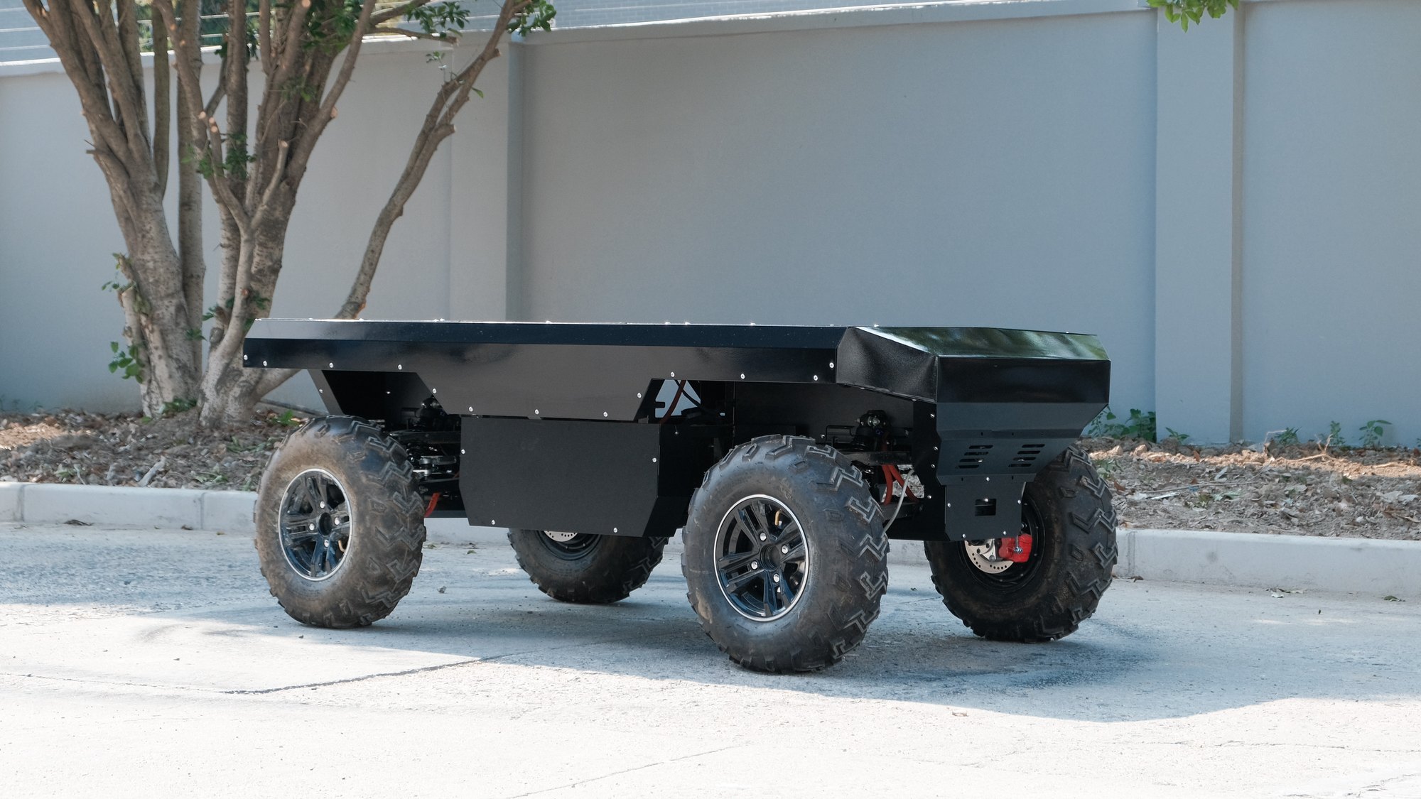
4×4 mobile platform for off-road robotic tasks. 1.0 provides the base chassis for integration; 2.0 organizes perception, positioning, compute and navigation into a system configuration.
An ideal data-collection platform: multiple cameras, LiDAR and fused positioning recorded on one vehicle
1.0 base chassis / 2.0 perception and autonomous navigation
2.0: 11 SENSING main cameras and an independent stereo positioning chain
Product configuration: ATX ×2, FTX180 ×4, mmWave radar ×2; OT128 as a data-collection extension
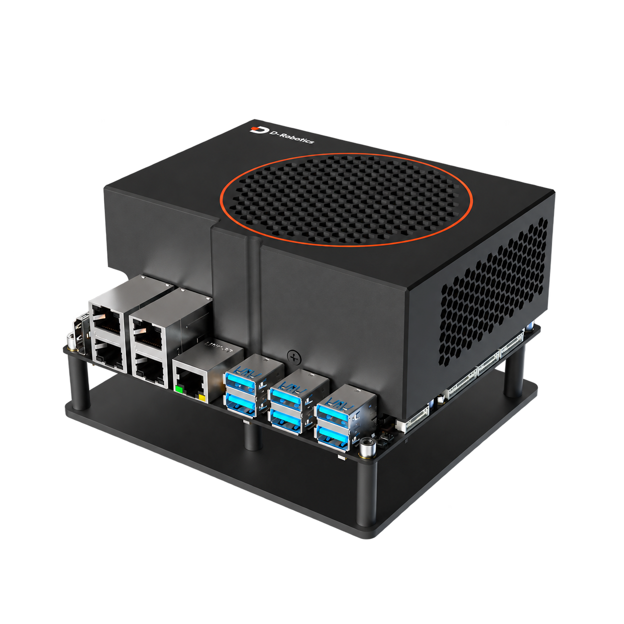
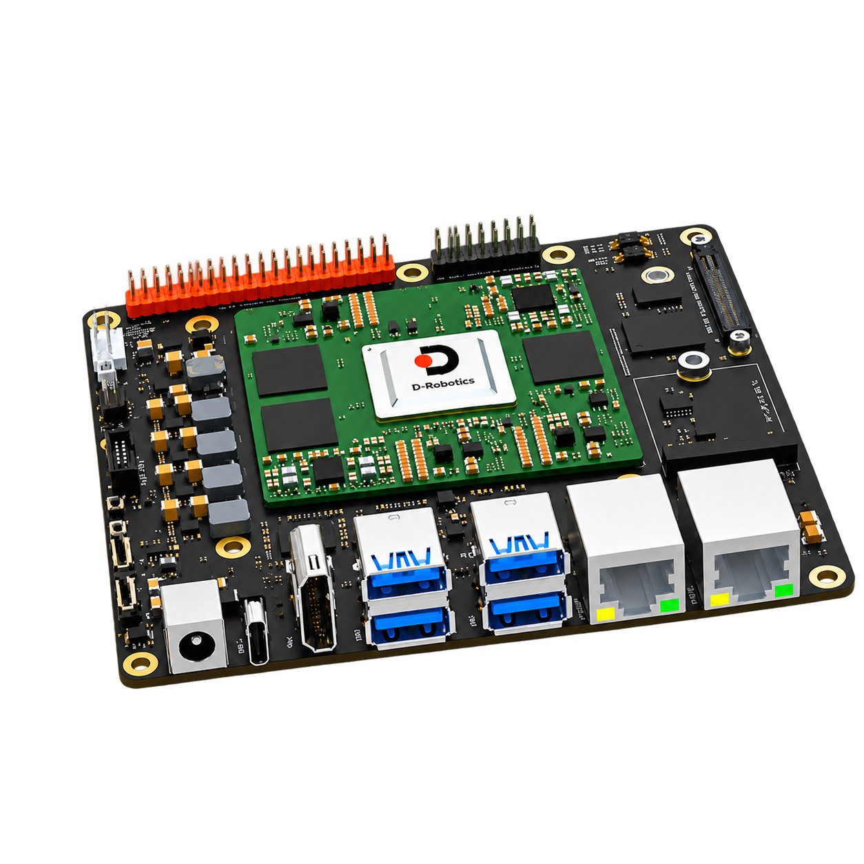
RDK compute: single S600 or dual S100P, handling camera input and compute/vehicle control respectively
Typical tasks
Outdoor robotics development
Industrial-park inspection and mobile perception
Autonomous navigation system integration for off-road environments
What to consider
Teams with their own autonomy software or payload can start with the 1.0 chassis version.
If you need integrated perception, positioning and navigation, choose 2.0 and define the mission route and operating conditions.
The chassis top speed, current firmware speed limit and autonomous operating speed are set separately and should not be treated as one figure.
Version and feature differences
Luchs B 1.0 · Base chassis version
Provides a mobile foundation for upper-layer software and payload integration, including chassis motion, remote control and control interfaces.
4×4 mobile chassis
Remote control and host control interfaces
Payload mounting and expansion base
Composition, compatibility and upgrades
Scope of this version
Body, drive, steering and brakes
Chassis controller and remote-control setup
Matching vehicle interfaces
Operating conditions
Autonomous navigation payload not included.
Check payload weight, center of gravity and power supply against the selected vehicle configuration.
Upgrades and expansion
When upgrading to 2.0, assess the vehicle firmware, mounting space, payload power and control interfaces before adding perception, positioning, compute and navigation components.
Luchs B 2.0 · Perception and autonomous navigation version
11 SENSING main cameras, independent fusion positioning, 2 ATX, 4 FTX180 and front and rear mmWave radar; single S600 or dual S100P compute option. The architecture must be validated for each task.
Perception and positioning system configuration
Navigation and vehicle control integration
Mission control station and communications setup
Composition, compatibility and upgrades
Scope of this version
Luchs B base chassis
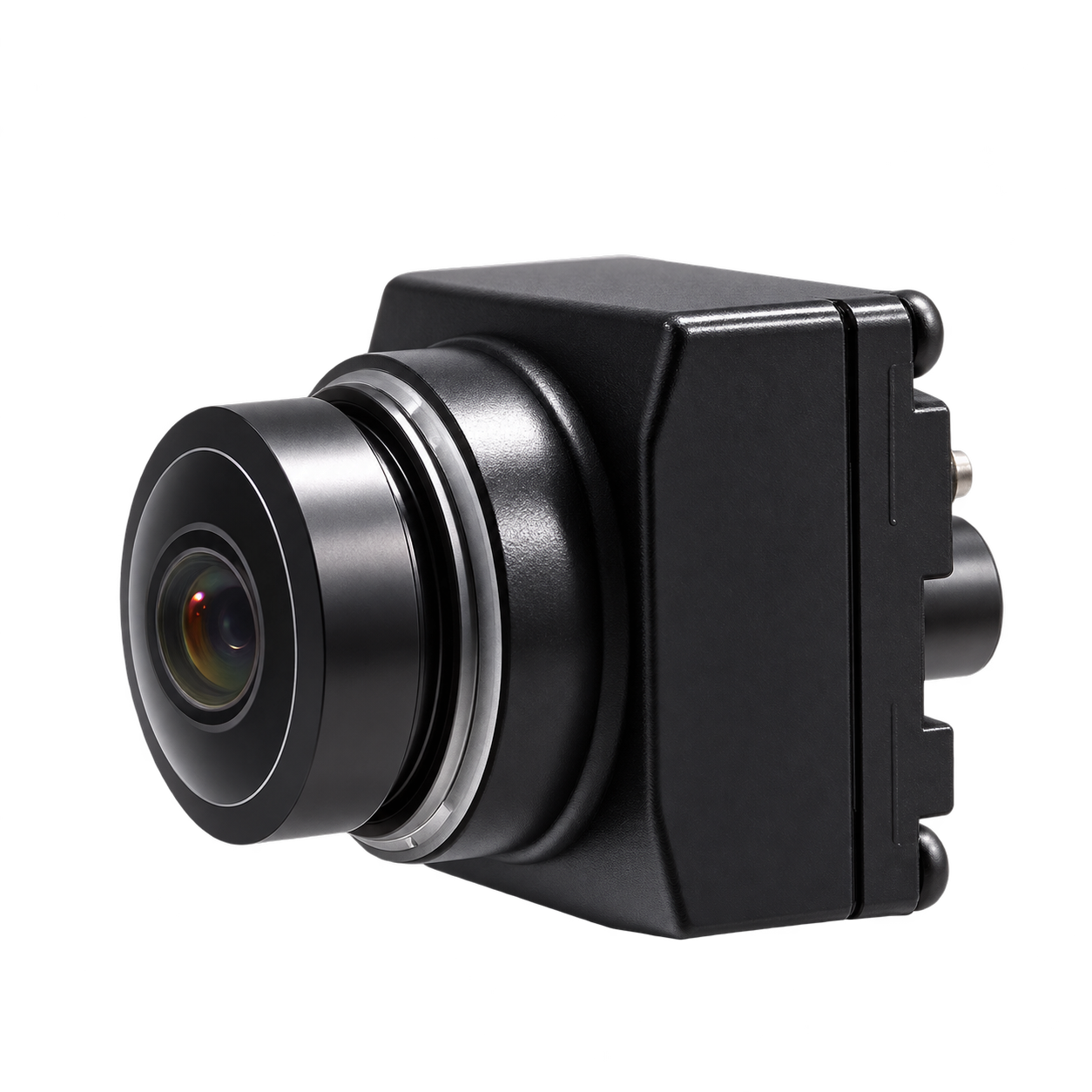
Main vision cameras: 11. Front 2, rear high-mounted 1, sides 4, near-field blind-spot 4; the exact model and output configuration for each position are confirmed in the inquiry.
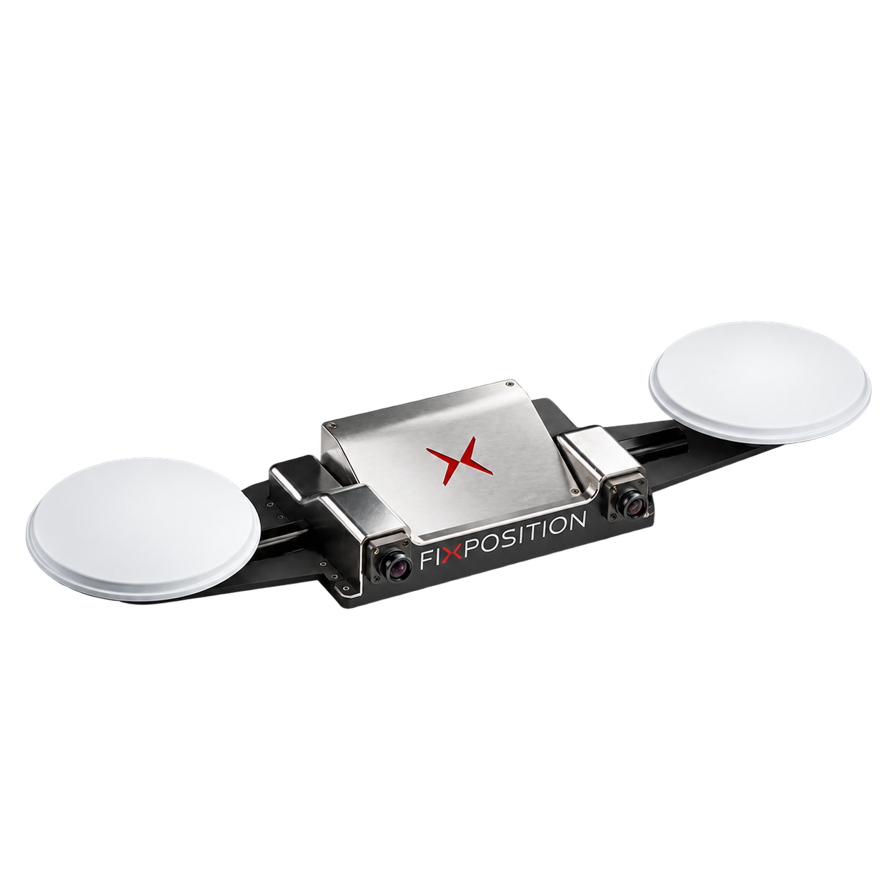
Fusion positioning: positioning unit, dual GNSS antennas, independent stereo camera. The independent stereo camera is not counted among the 11 main cameras; restricted documentation is not cited in detail.
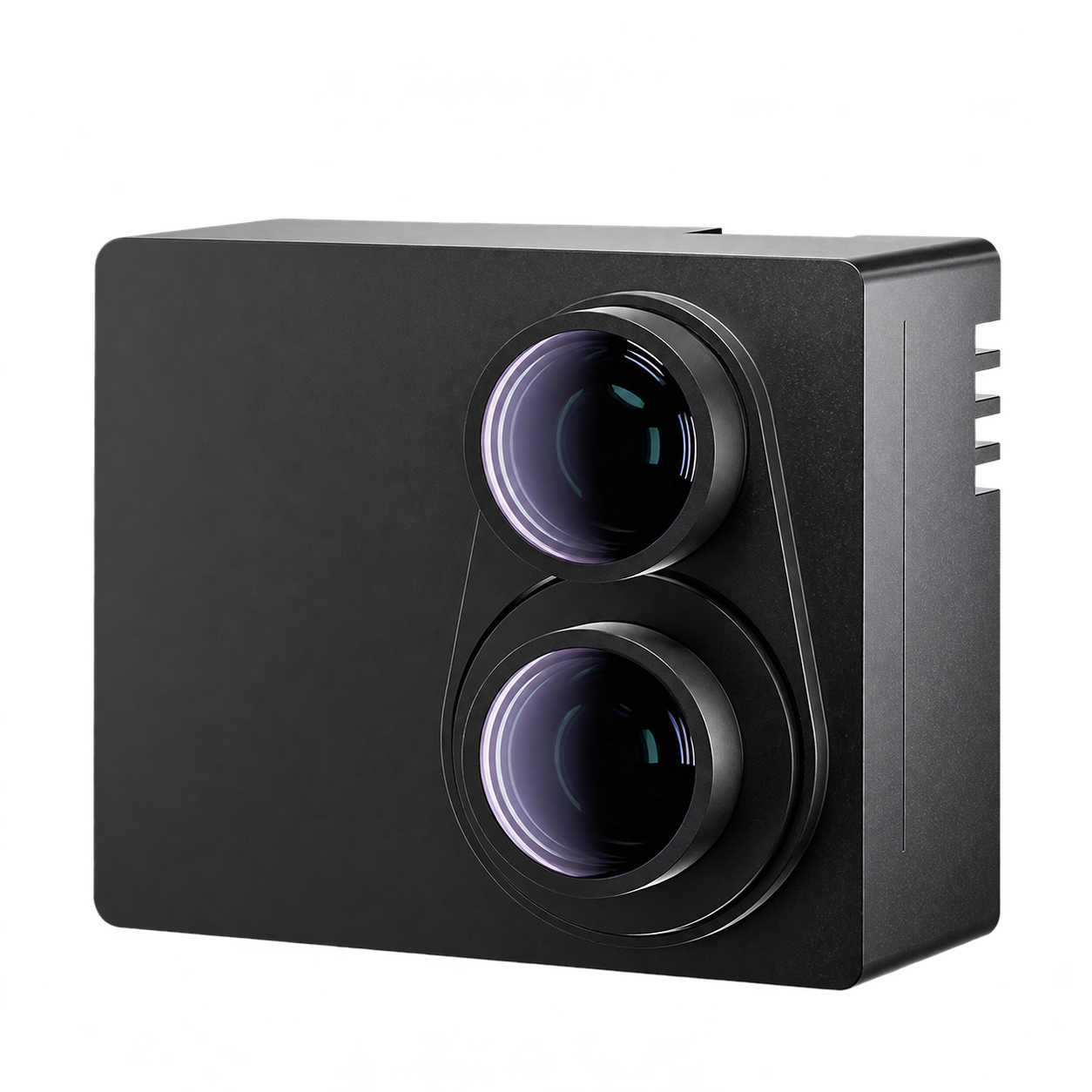
Product LiDAR: ATX ×2; FTX180 ×4. One ATX front and one rear; one FTX180 each at front, rear, left and right.
Millimeter-wave radar: 2. One front, one rear; BSR403T3 is an optional model. CAN, power supply, packaging and software integration to be confirmed.
Compute options: single S600 / dual S100P. With dual S100P, node A receives all 11 main cameras; node B handles edge computing and vehicle-control transmission. The nodes cooperate over the sensor network.
Data-collection extension: OT128 optional. Not included in the product configuration by default; the corresponding Gigabit T1 branch is costed separately.
Operating conditions
Camera concurrency, synchronization and algorithm performance are verified per project configuration.
Operating area, speed, takeover mode and sensor coverage together define the scope of use.
Dual-light gimbal, range extender and dual batteries are not included as standard; aviation connectors, fuses, wire gauge and DC/DC model are determined by the specific electrical configuration.
Upgrades and expansion
Sensors or compute can be expanded for the task; after changing the mounting or equipment combination, update calibration, drivers and vehicle parameters accordingly.
Choose a build; mounting and accessory needs can be added to your inquiry.
Specifications & Interfaces
Switches the displayed specifications only. Purchase and inquiry configurations are selected separately.
Key specifications
Platform type
4 × hub motors, 72 V
Payload
80 / 250 kg
Conditions
Chassis specifications
Working load and maximum load correspond to different usage conditions
Speed
30 km/h
Conditions
Corresponds to the firmware described in the manual
Battery configuration
72 V 60 Ah / 73 V 127.4 Ah
Conditions
Battery and charger depend on the selected vehicle configuration
Control and communication
Vehicle control interface: VCU V2.6
CAN physical layer: CAN 2.0B; baud rate matches firmware and protocol version
Dimensions & Weight
Size: 1990 × 1150 × 800 mm
Weight: 230 kg
Operating environment
−20 °C–+55 °C
Additional measured specifications
Additional measured specifications
Perception and positioning scope
Main vision cameras: 11
Fusion positioning: positioning unit, dual GNSS antennas, independent stereo camera
Product LiDAR: ATX × 2; FTX180 × 4
Millimeter-wave radar: 2
Data-collection extension: OT128 optional
Conditions
Front 2, rear high-mounted 1, sides 4, near-field blind-spot 4
The independent stereo camera is not counted among the 11 main cameras
One ATX front and rear; one FTX180 front, rear, left and right
One front, one rear
Not included in product configuration by default
Gigabit T1 branch costed separately
Other power & installation specifications
Other power & installation specifications
Motor power and rating basis
1.8 / 5 kW
Conditions
per motor
Other interfaces & features
Other interfaces & features
Ground clearance
300 mm
System & software scope
Vehicle protocol, DBC and ROS software packages, matched by firmware
Compute configuration
Single S600 / dual S100P
Conditions
Dual S100P: node A receives all 11 main cameras
Node B handles edge computing and vehicle-control transmission; both nodes cooperate over the sensor network
Functional scope by version
1.0 base chassis: chassis motion, remote control and vehicle control interface
2.0 perception and autonomous navigation: base chassis + perception and positioning payload + compute and navigation configuration
Conditions
Navigation functions, sensors and operating conditions depend on the configuration.
Road use conditions
Not permitted per the manual
Key specifications
Platform type
4 × hub motors, 72 V
Payload
80 / 250 kg
Conditions
Chassis specifications
Working load and maximum load correspond to different usage conditions
Speed
30 km/h
Conditions
Corresponds to the firmware described in the manual
Battery configuration
72 V 60 Ah / 73 V 127.4 Ah
Conditions
Battery and charger depend on the selected vehicle configuration
Control and communication
Vehicle control interface: VCU V2.6
CAN physical layer: CAN 2.0B; baud rate matches firmware and protocol version
Dimensions & Weight
Size: 1990 × 1150 × 800 mm
Weight: 230 kg
Operating environment
−20 °C–+55 °C
Other power & installation specifications
Other power & installation specifications
Motor power and rating basis
1.8 / 5 kW
Conditions
per motor
Other interfaces & features
Other interfaces & features
Ground clearance
300 mm
System & software scope
Vehicle protocol, DBC and ROS software packages, matched by firmware
Functional scope by version
Chassis motion, remote control and vehicle control interface
Road use conditions
Not permitted per the manual
Key specifications
Platform type
4 × hub motors, 72 V
Payload
80 / 250 kg
Conditions
Chassis specifications
Working load and maximum load correspond to different usage conditions
Speed
30 km/h
Conditions
Corresponds to the firmware described in the manual
Battery configuration
72 V 60 Ah / 73 V 127.4 Ah
Conditions
Battery and charger depend on the selected vehicle configuration
Control and communication
Vehicle control interface: VCU V2.6
CAN physical layer: CAN 2.0B; baud rate matches firmware and protocol version
Dimensions & Weight
Size: 1990 × 1150 × 800 mm
Weight: 230 kg
Operating environment
−20 °C–+55 °C
Additional measured specifications
Additional measured specifications
Perception and positioning scope
Main vision cameras: 11
Fusion positioning: positioning unit, dual GNSS antennas, independent stereo camera
Product LiDAR: ATX × 2; FTX180 × 4
Millimeter-wave radar: 2
Data-collection extension: OT128 optional
Conditions
Front 2, rear high-mounted 1, sides 4, near-field blind-spot 4
The independent stereo camera is not counted among the 11 main cameras
One ATX front and rear; one FTX180 front, rear, left and right
One front, one rear
Not included in product configuration by default
Gigabit T1 branch costed separately
Other power & installation specifications
Other power & installation specifications
Motor power and rating basis
1.8 / 5 kW
Conditions
per motor
Other interfaces & features
Other interfaces & features
Ground clearance
300 mm
System & software scope
Vehicle protocol, DBC and ROS software packages, matched by firmware
Compute configuration
Single S600 / dual S100P
Conditions
Dual S100P: node A receives all 11 main cameras
Node B handles edge computing and vehicle-control transmission; both nodes cooperate over the sensor network
Functional scope by version
Base chassis + perception and positioning payload + compute and navigation configuration
Conditions
Navigation functions, sensors and operating conditions depend on the configuration.
Road use conditions
Not permitted per the manual
Components & Accessories
Product & configuration scope
Luchs B 4×4 chassis with selected control configuration
2.0 adds perception, positioning, compute and navigation software according to the version breakdown below
Electrical, mechanical and software interface documentation matching the delivered configuration
Accessory selection
Payload mounting structure and payload power supply
Sensors, compute and networking for the corresponding version
Control station, communication links and mission-specific accessories
Included items, options, wiring harnesses and mounting hardware are confirmed according to the selected model and system configuration.
Software and usage support
Chassis interfaces correspond to the firmware version on the actual vehicle.
For 2.0, TerraAgent (TAR) positioning, perception, planning and control integration can be selected according to the required functional scope.
The RDK compute configuration must match the sensor drivers, navigation software and chassis interface.
Operating conditions
Per the manual, operate only on permitted sites, not on public roads.
Confirm the current firmware and control interface first; during development and testing, have a safety operator present and keep the emergency stop available.