system configuration · Scientific research and mobile Robotics
Luchs A robot development bundle
Combine Luchs A in your chosen build with RDK, vision and positioning components to grow from chassis control to mobile perception and navigation development.
Mobile Robot Course Path following and control research vision positioning algorithm development
The following describes the role of each module in the system; the actual connection depends on the selected device interface and software configuration.
01
chassis configuration
Select DF, FA, DA or 4WS by motion model.
02
perception and positioning
adds vision and positioning devices by task.
03
RDK calculation
selects calculation configurations by model and interface load.
04
control interface
connects chassis status and motion instructions to application software.
Available range
A Luchs A chassis configuration
A matching set of RDK compute configurations
Optional vision, positioning and integration support
Steers by left/right wheel-speed difference, 0 m pivot radius; suited to skid-steer motion-model development.
Skid-steer motion model
Pivot turn
40 kg · 800 × 665 × 292 mm
FA · Former Ackerman
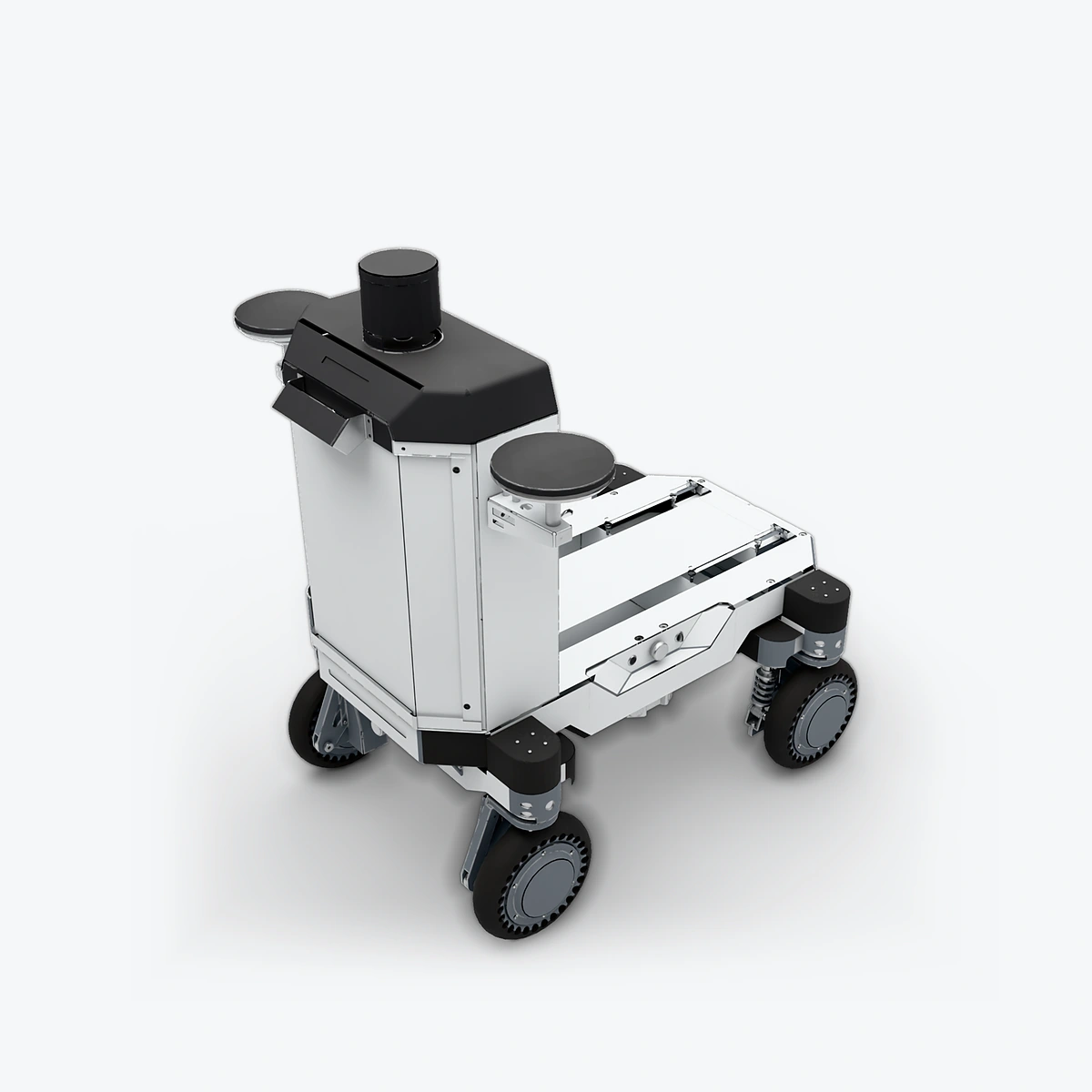
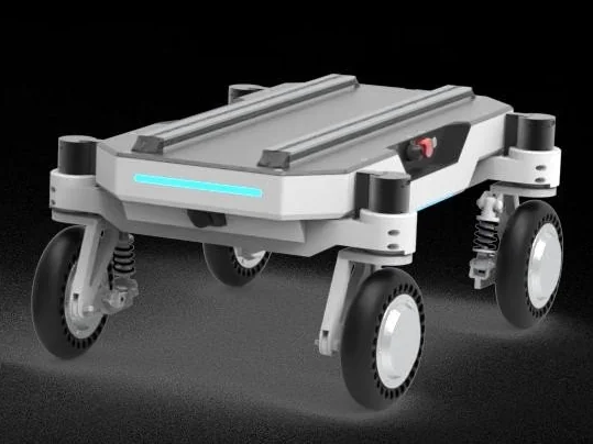
Product render
Front Ackermann steering with 0.89 m minimum Ackermann radius, plus skid-steer pivot turns; suited to car-like path tracking and control development.
Skid-steer and Ackermann motion models
1 × 140 W steering servo
45 kg · 800 × 665 × 292 mm
DA · Double Ackerman
Product render
Both axles steer, 0.445 m minimum dual-Ackermann radius; suited to multi-axle steering and maneuverability research.
Skid-steer, Ackermann and dual-Ackermann motion models
1 × 140 W steering servo
50 kg · 800 × 665 × 292 mm
4WS · four-wheel steer
Product render
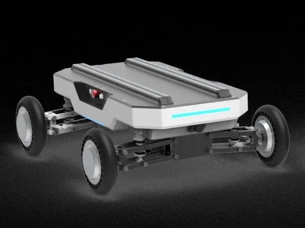
Independent four-wheel steering with pivot turns and sideways (crab) travel, 0.857 m pivot clearance circle: the most flexible base for robot motion research.
Skid-steer, Ackermann, dual-Ackermann and four-wheel-steer motion models
4 × 140 W steering servos, independent swing-arm suspension
55 kg · 800 × 580 × 372 mm; IP54-sealed build available
Installation and connection conditions
The mechanical, electrical, and software interfaces between devices collectively determine system configuration.
Mechanical and Payload
mounting components must be included in the total Payload and center of gravity to avoid blocking the camera's field of view.
chassis communication
CAN protocol, ROS drive and vehicle model parameters correspond to the selected configuration.
Cameras & positioning
camera driver, positioning coordinate system and data timestamp must be consistent.
Configure the entire solution
Select the version and number of sets, and select products in the same place. included in package, additional items and customer-supplied are listed separately.
Preparing configuration options. The complete solution will be saved as a set of products, with included in package, additional items and customer-supplied listed separately.
 Germany
 Netherlands
 Switzerland
 Austria
 Norway
 Finland